
I have only the basic edition of Silhouette Studio where direct import of the SVG format is not possible. To overcome this (without spending money on the designer edition) I usually convert to DXF or in some cases PNG and use the trace function in Silhouette Studio. For overlapping designs or lines the PNG solution is not suitable. But for DXF I have had some accuracy issues and would like to dig deeper into this. You are invited on the journey from Inkscape and SVG to DXF to Silhouette Studio. For those of you not interested in the full journey I will start with the summary of what I recommend.
Conclusions first – for the busy ones
- Prepare your SVG file with
- Use same colour for paths you want to connect (colors define the compound paths in Silhouette Studio
- Convert text to path (if else it will not show up)
- Convert objects to path if you want them to join a compound path
- Increase node density on curves fx select all nodes and press add nodes to double the nodes (once is often sufficient and possibly the better if you don’t follow the next step)
- Blow up the design so that it extend your Inkscape document. This will improve precision and solve most problems. Then you could increase the node density even more too without having trouble.
- Use “Save a copy” instead of “Save as” for more convenience
- Use DXF R14 with ROBO selected and px as base unit
- Verify the paths. Distortions might be fixed by
- Increase the size of the design in Inkscape and add more nodes (this probably will do the trick)
- Try rotating your design fx by 45 degrees to trigger another rendering (might also get worse)
- You might get lucky on selecting pt or px as base unit instead of mm
- Try the LWPOLYLINE option instead (it might fix one problem and create some new)
- Consider R12 to have your design split into small straight line segments and no random distortions – use absolute coordinates to avoid transformation matrixes
- Consider if exporting PNG is an option fot your current design
- Consider buying designer edition of Silhouette Studio…
- If you have added a lot of nodes – check whether simplify in Silhouette Studio can be done without distorting the paths.
Increase the number of nodes before converting
One well known fix when there is an accuracy problem with DXF files is to increase the density of nodes to better describe the cruves. I have usuall marked all nodes and then pressed the add nodes button a few times. But sometimes this does not work well either even with extreeme dense nodes. I addition it is quite cumbersome and might give some trouble with slow performance in Silhouette Studio or cutting process. If you like to use the “line segment overcut” option to get nice corners this might end up with your machine overcutting a bunch of nodes and messing up your curves (talking from experience…).
Spline output or line output?
I’ve seen different behavior if I choose the ROBO-Master spline output or the LWPOLYLINE output. The tutorials I have seen differ in their recommandations. Is there a way to get control and have the perfect outcome each time?
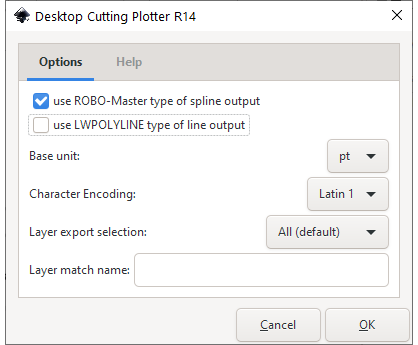
Inkscape v1.0 – R12 or R14?
I recently upgraded to Inkscape v1.0 and found that now there is two DXF file types to choose; R12 or R14. From this link I find that R14 is a newer format than R12, but both are pre 2000 så both are old AutoCAD filetypes. R14 support splines (curves), but R12 only spport straight lines. (If you would like to know detalils about the format you could read the Autodesk DXF reference.)
When I try to save as R12 type I do not get the question about ROBO or LWPOLYLINE. Saving as R14 seems similar to what was the case in earlier versions of Inkscape. There is a Help tab showing that paths (lines and splines) are supported for R14 and also rectangles. This info also says that ROBO is just for ROBO-Master and AutoCAD. I understand that as an warning that Silhouette Studio might not understand the ROBO format correct.
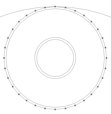
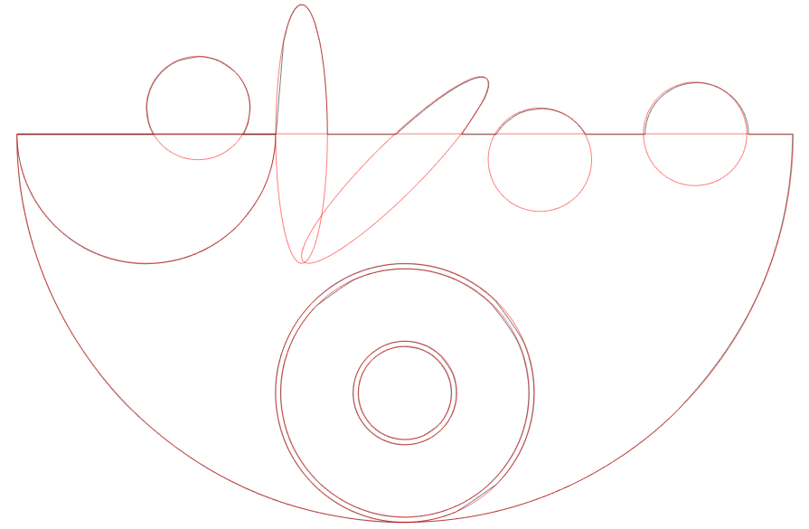
The test pattern in SVG format
As a circle is easy to see inaccuracies on I will use that as an base for my test drawing. And I would like like some sharp curves and different angles on corners. I constructed this test design both in Inkscape v 1.0 and in Silhouette Studio version 4.4.247ss (both latest versions available pr august 2020 and all on Windows 10). Now I was able to test accuracy and behavior of different settings.
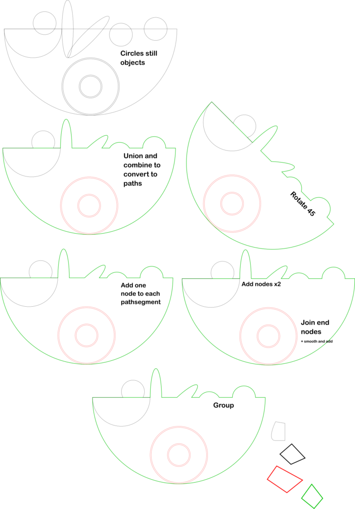
Converting to DXF
As for now the base unit in the R14 dialog box is kept at “mm”. I will come back to this later in this journey.
For each export I used “Save a copy” not the “Save as”. I’m not sure if it is a new v1.0 feature, but I was glad to find it. This exports to DXF without closing the current SVG.
The export settings used for the test:
- R12
- R14 – neither ROBO nor LWPOLYLINE selected
- R14 – ROBO
- R14 – LWPOLYLINE
- R14 – both selected
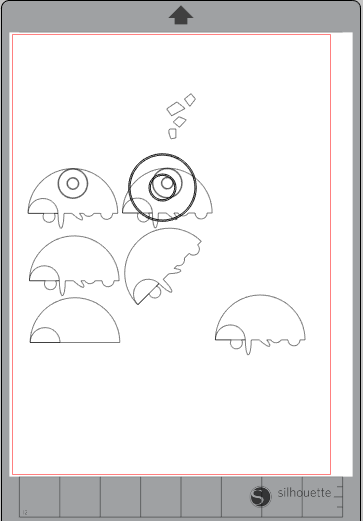
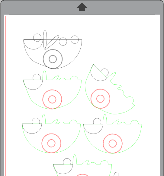
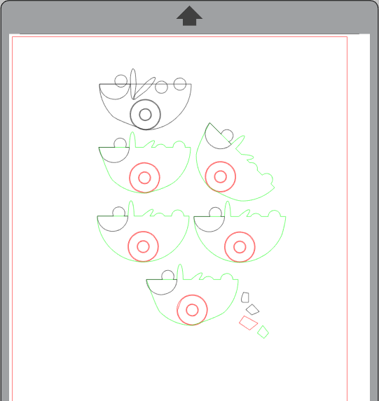
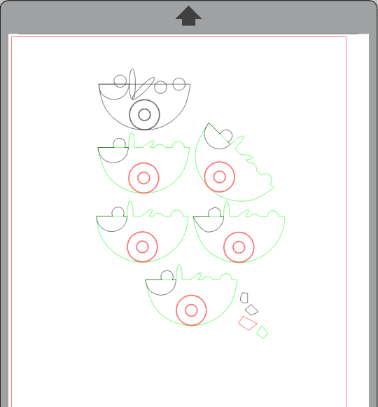
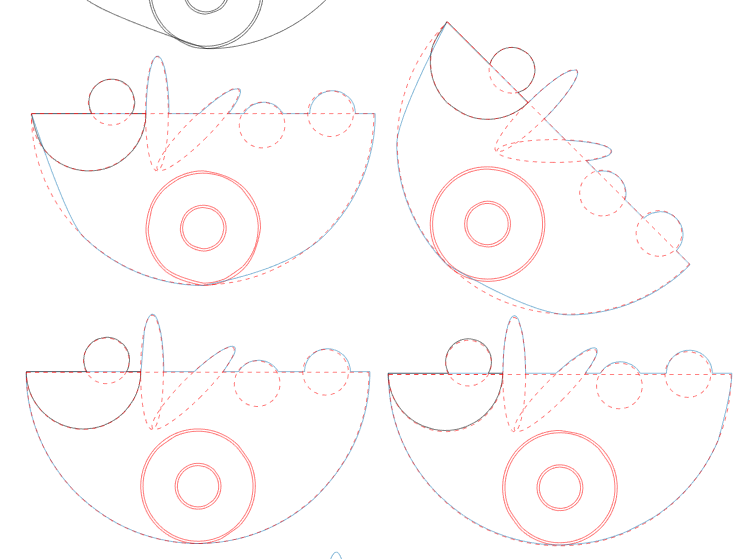
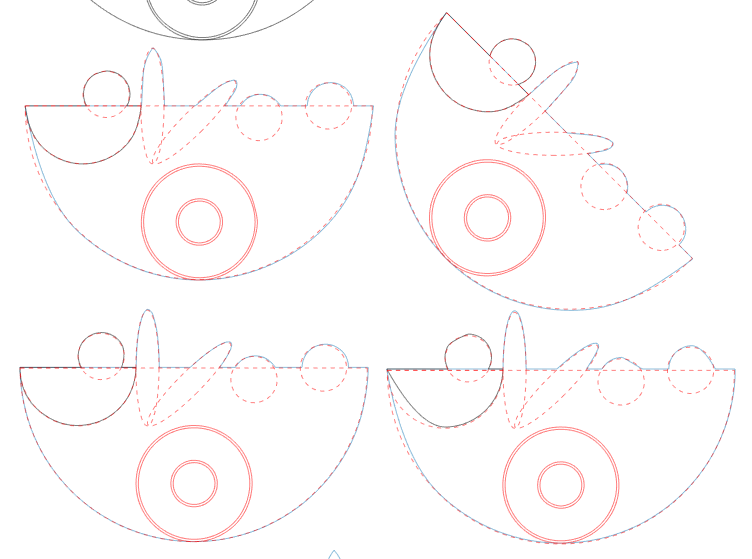
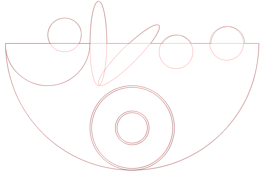
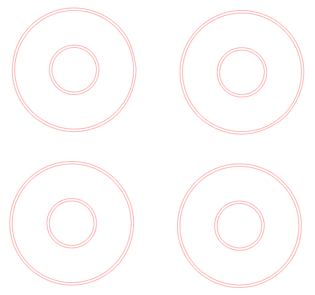
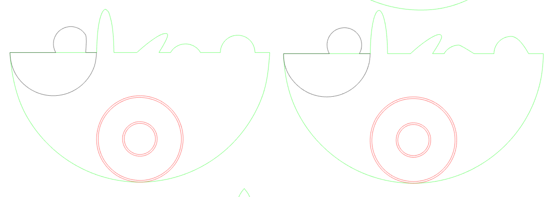
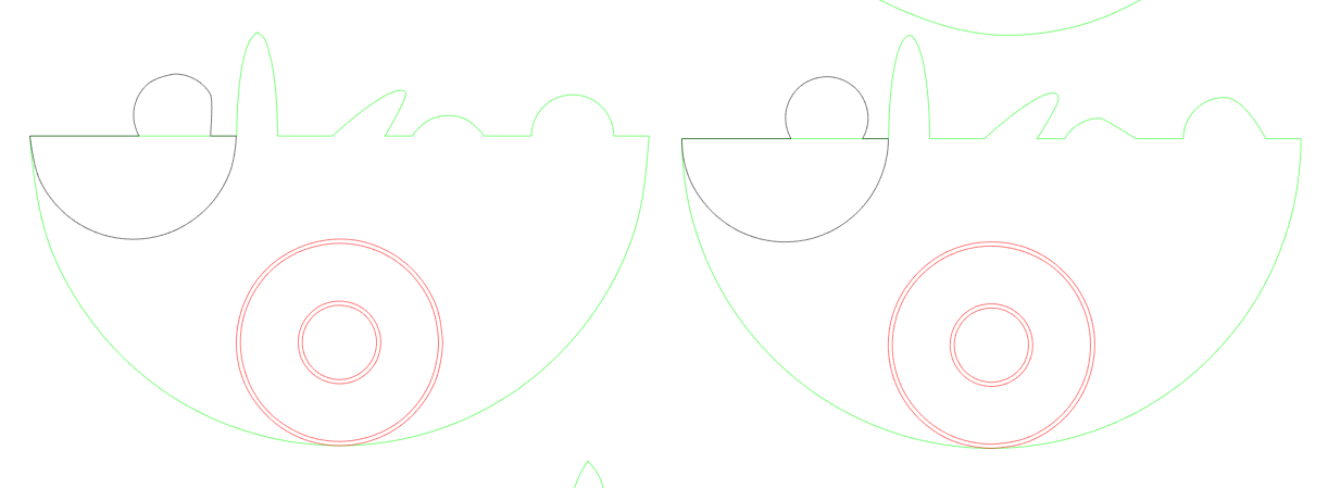
First impression in Silhouette Studio
Here comes a gallery of the first impression when opening in Silhouette Studio. Go back to the image above to see what the different variants are. The lower variant (the group) did nothing else than the same ungrouped variant so grouping has no effect on compound paths f.x. Click on the images to zoom in and read the captions.
. All in one compound path.")


.")
. Most severe distortions seen where the most nodes were added (adding twice).")


DXF R12 format
R12 should not support splines. So what will it do with the circles?
The shapes look very good with no distortions, but when zooming in one can see that this is rendered as small straight lines. Simplify will convert the paths to curves, but also distort the paths somewhat. If you think this is no good for you – scroll to next chapter; R14 format.
Checking the nodes show that there is no difference in number of nodes on the curves where nodes were added, only on the straight lines (same nodes as in the SVG).
When opened in Silhouette studio the first thing you will see is that the image is flipped upside down (no problem) and that some relative positions and rotations are not correct. I recognize this as transformation matrixes in the xml is not considered. To fix this you could ungroup everything and then change SVG output preferences to absolute, select all, press arrow up, arrow down to trigger re-writing the paths to absolute. This will not help on objects, just paths.
DXF R14 format
Shapes as objects
Neither R12 nor R14 can handle text as objects. These will not show up. I’ve seen rectangles, stars and circles as objects showing up. For ROBO (and ROBO+LW) these objects look correct with no distortion, but for LWPOLYLINE or none selected the circles are significatly distorted.
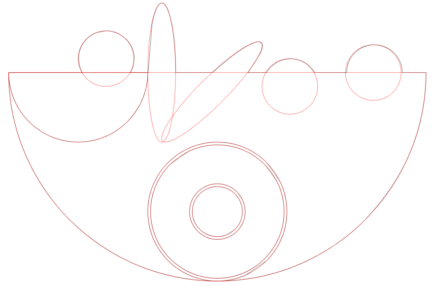
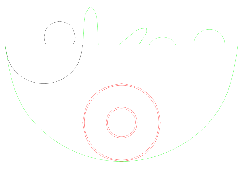
Paths
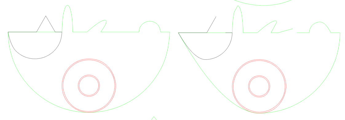
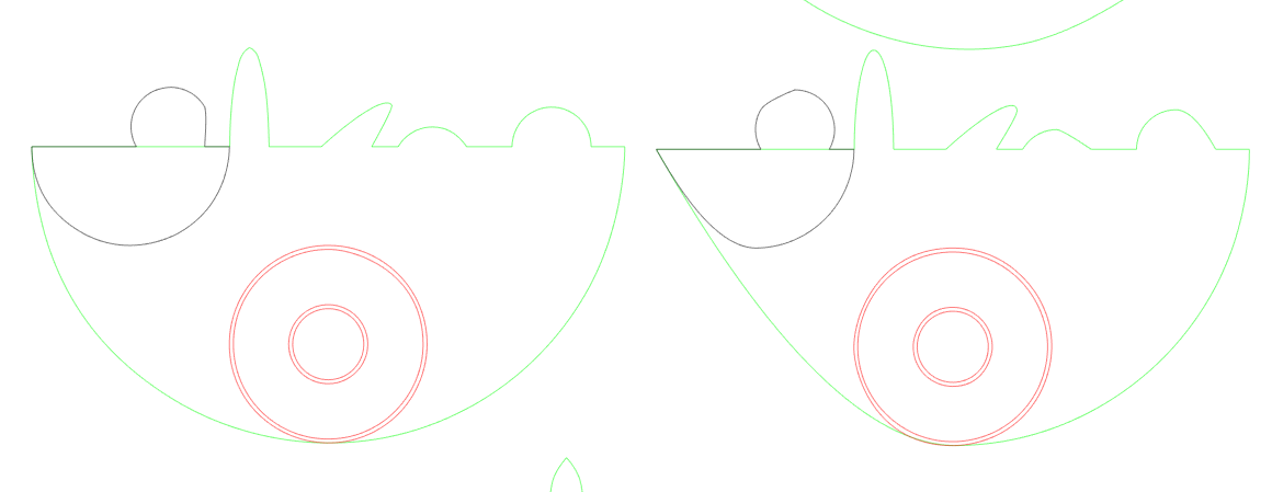
All R14 settings had distortions of curves. Some of these are already seen in the gallery above. Now let us zoom in on the details.


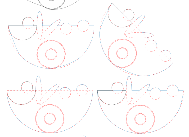
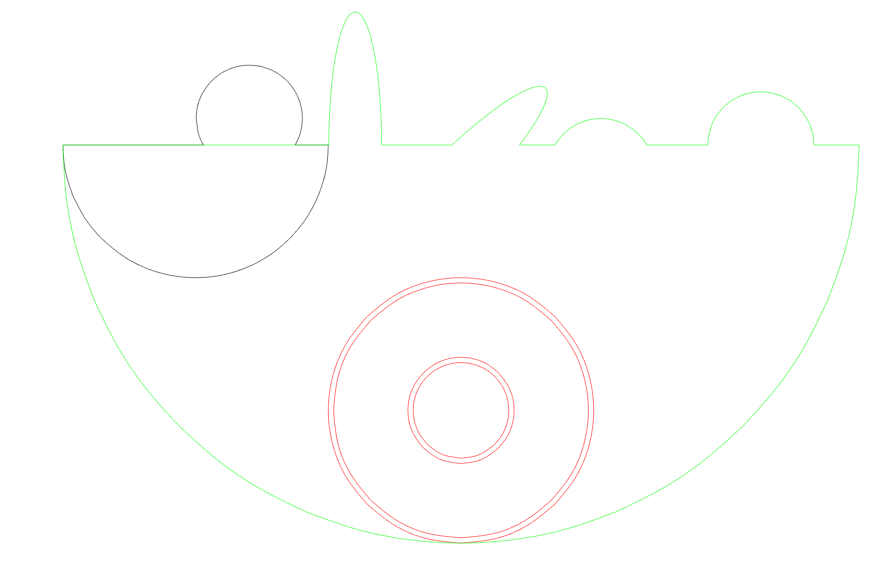
And then let us zoom in on the best version from all: adding nodes once. I have changed the colors to all black and added the original design on top (I think I have failed slightly with the position of the two circles to the right between Inkscape and Silhouette Studio so please ignore the details in position there.


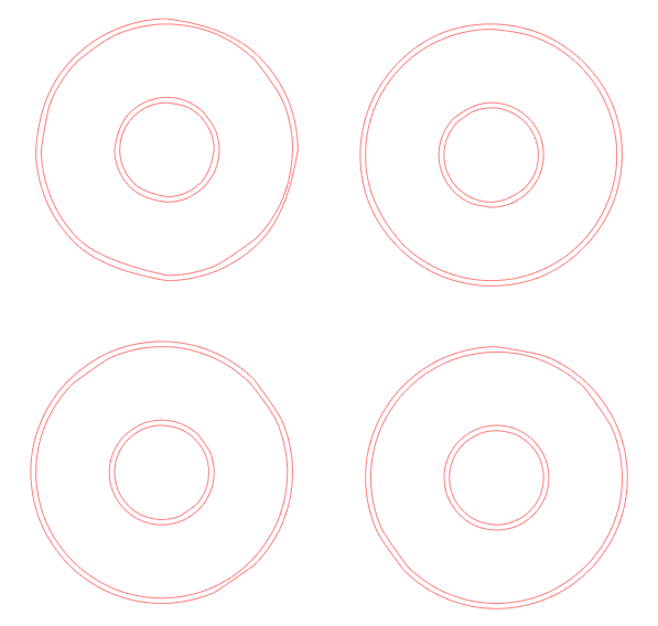
Next up is a closeup on the concentric circles.
 actually is very good. Forced rerendering that got lucky?")

. Upper right = again rotated is better than unrotated. Lower row = once and twice adding nodes, quite good.")

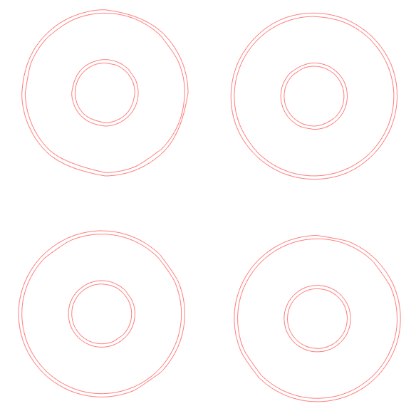
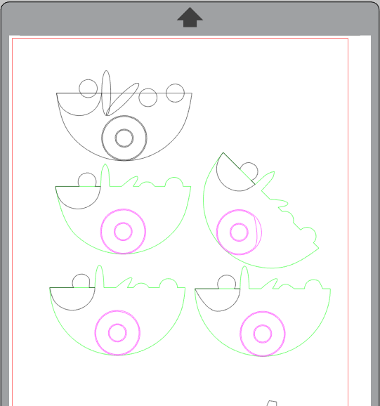
Base unit setting
How do the base unit setting affect the result?
All node coordinates are saved as floating numbers with 6 decimals. Selecting meter (which is pretty extreme in the world of Silhouette Studio) compared to mm the precision of the coordinates will be reduced by 3 digits (1/1000). So the best precision you will have if you select a small unit.
Here comes the results for the variants with added nodes once and twice (all with ROBO selected). Best precision is seen with the smallest base units as expected.


One could export layer by layer but there is a risk that the sizing will differ. Maybe drawing a bounding box rectangel in each layer could do that trick if the design is complicated.
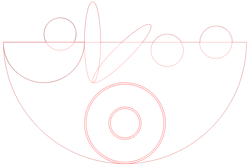
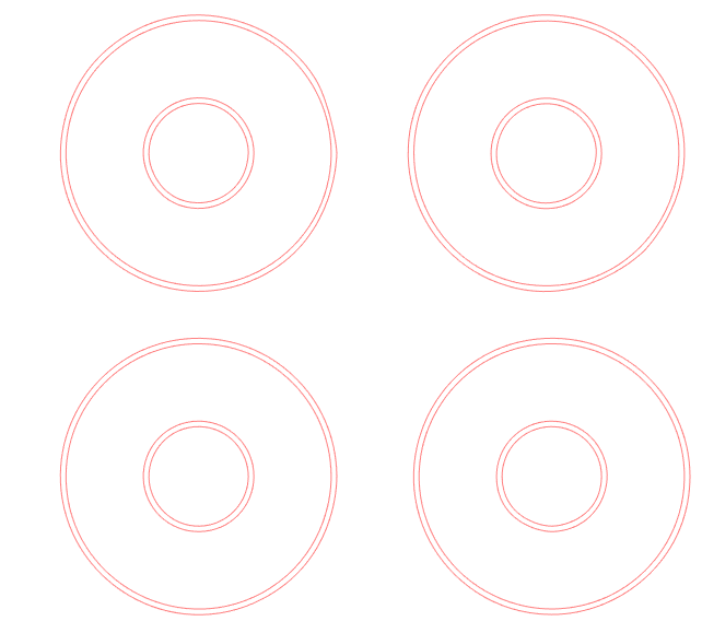
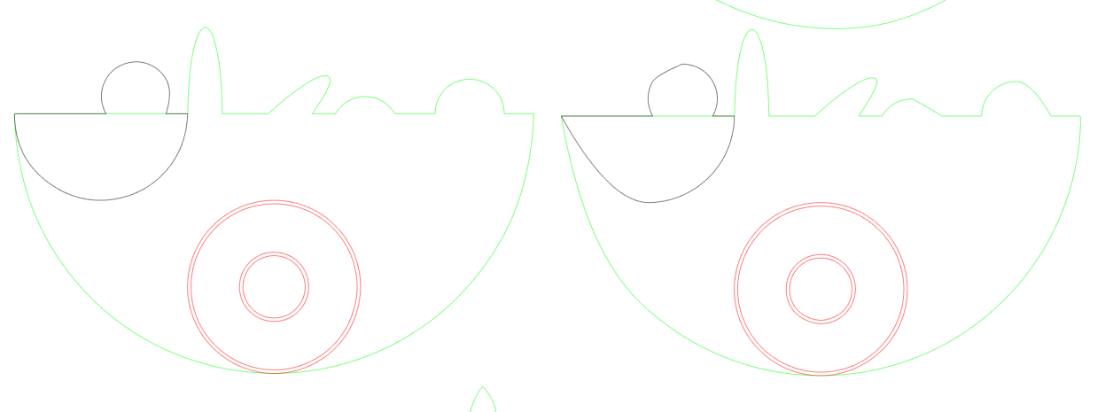
Big original
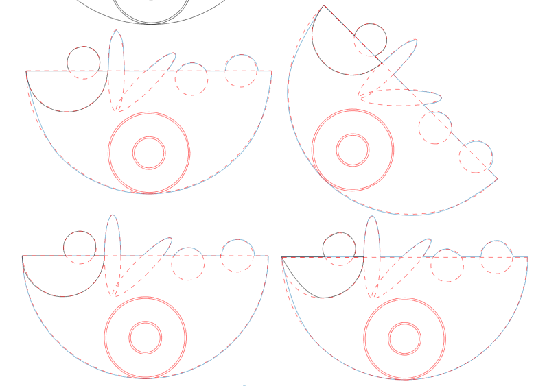
Now – what if I blow up the design in Inkscape before exporting to DXF? What will that do to the precision?
I took the first variant with no extra nodes and the variant with nodes added twice. Both were separately copied to a new Inkscape document and blown up by 10 (exceeding the page). Then i used the ROBO selection and px as base unit. The one with nodes added twice had a perfect rendering in Silhouette Studio. The one with no added nodes had issues with distorition. I also tried to add nodes twice more on the one where there already were added nodes twice (i.e. 2^4 more nodes than original). This result were also perfect – no new artifacts introduced. Even simplify in Silhoette Studio did not change the shapes. I also resized the full collection of variants in the original file together. It worked too. YEAY!
. The curves are not well rendered.")
. The curves are perfect. This was the variant where strange artefacts occured with the original size.")
Conclusions
Problem (with this design type) solved. I’ve seen trouble still with other design types. To be continued…
I’ve put the summary on top.
Thank you so much for this tutorial. I followed your instructions on how to use single line SVG fonts in Inkscape as well. Game changer!